Building Statistics
|
|||||||||||||||||||||||||||||||||||||||||||||||||||||||||||||||||||||||||||||||||||||||||||||
General Building Data: |
|||||||||||||||||||||||||||||||||||||||||||||||||||||||||||||||||||||||||||||||||||||||||||||
Building Name: |
Virtua Replacement Facility |
||||||||||||||||||||||||||||||||||||||||||||||||||||||||||||||||||||||||||||||||||||||||||||
Location: |
Camden County |
||||||||||||||||||||||||||||||||||||||||||||||||||||||||||||||||||||||||||||||||||||||||||||
Voorhees, New Jersey
| |||||||||||||||||||||||||||||||||||||||||||||||||||||||||||||||||||||||||||||||||||||||||||||
Function: |
Medical Building |
||||||||||||||||||||||||||||||||||||||||||||||||||||||||||||||||||||||||||||||||||||||||||||
Size: |
642,000 Square Feet |
||||||||||||||||||||||||||||||||||||||||||||||||||||||||||||||||||||||||||||||||||||||||||||
Site Size: |
120 Acres |
||||||||||||||||||||||||||||||||||||||||||||||||||||||||||||||||||||||||||||||||||||||||||||
Floors Above Ground: |
8 Floors |
||||||||||||||||||||||||||||||||||||||||||||||||||||||||||||||||||||||||||||||||||||||||||||
Total Levels: |
9 Floors |
||||||||||||||||||||||||||||||||||||||||||||||||||||||||||||||||||||||||||||||||||||||||||||
Start Date of Construction: |
March 17, 2008 |
||||||||||||||||||||||||||||||||||||||||||||||||||||||||||||||||||||||||||||||||||||||||||||
Predicted End Date of Construction: |
March 31, 2011 |
||||||||||||||||||||||||||||||||||||||||||||||||||||||||||||||||||||||||||||||||||||||||||||
Project Delivery Method: |
CM @ Risk with |
||||||||||||||||||||||||||||||||||||||||||||||||||||||||||||||||||||||||||||||||||||||||||||
Guaranteed Maximum Price |
|||||||||||||||||||||||||||||||||||||||||||||||||||||||||||||||||||||||||||||||||||||||||||||
Actual Cost Information: |
Construction GMP - $323 Million |
||||||||||||||||||||||||||||||||||||||||||||||||||||||||||||||||||||||||||||||||||||||||||||
Estimated Owner's Cost - $450 Million |
|||||||||||||||||||||||||||||||||||||||||||||||||||||||||||||||||||||||||||||||||||||||||||||
Historical Requirements: |
There were no historical requirements |
||||||||||||||||||||||||||||||||||||||||||||||||||||||||||||||||||||||||||||||||||||||||||||
Relevant Codes: |
IBC 2000 |
||||||||||||||||||||||||||||||||||||||||||||||||||||||||||||||||||||||||||||||||||||||||||||
AIA Guidelines for Design & Construction of Hospital & Health Care Facilities, 2006 |
|||||||||||||||||||||||||||||||||||||||||||||||||||||||||||||||||||||||||||||||||||||||||||||
NFPA Ch. 101, 2000 |
|||||||||||||||||||||||||||||||||||||||||||||||||||||||||||||||||||||||||||||||||||||||||||||
Hospital Licensing Standards - New Jersey Department of Health and Senior Services, Latest Edition |
|||||||||||||||||||||||||||||||||||||||||||||||||||||||||||||||||||||||||||||||||||||||||||||
Standard for Licensing of Ambulatory Care Facilities |
|||||||||||||||||||||||||||||||||||||||||||||||||||||||||||||||||||||||||||||||||||||||||||||
Zoning Requirements: |
|||||||||||||||||||||||||||||||||||||||||||||||||||||||||||||||||||||||||||||||||||||||||||||
The Virtua Hospital is in the Major Business (MB) District of the Voorhees Township Zoning Codes. The hospital can also apply for exclusion from some of the requirements specific for the MB district. Some of the specific exclusions to the zoning code are listed below: |
|||||||||||||||||||||||||||||||||||||||||||||||||||||||||||||||||||||||||||||||||||||||||||||
Minimum setback of the building from Rt. 73 |
100 feet | ||||||||||||||||||||||||||||||||||||||||||||||||||||||||||||||||||||||||||||||||||||||||||||
Minimum setback of the building from residential areas |
200 feet |
||||||||||||||||||||||||||||||||||||||||||||||||||||||||||||||||||||||||||||||||||||||||||||
Minimum setback of the parking area from residential areas |
100 feet |
||||||||||||||||||||||||||||||||||||||||||||||||||||||||||||||||||||||||||||||||||||||||||||
Maximum height of the building |
50 feet, plus 4 feet every 5 feet setback, |
||||||||||||||||||||||||||||||||||||||||||||||||||||||||||||||||||||||||||||||||||||||||||||
maximum height - 145 feet |
|||||||||||||||||||||||||||||||||||||||||||||||||||||||||||||||||||||||||||||||||||||||||||||
There are also many other requirements, beyond the changes in setbacks and height restrictions. For example, the medical campus must provide community benefits and uses. Also, the maximum amount of clearing of the site is 70%. The Building must also cover less than 25% of the site and have less than 60% impervious coverage. There must also be a one to one ration of hospital uses and non-hospital uses inside the building. Some example of non-hospital uses are medical clinics, offices, labs, conference rooms, and restaurants, that are only used by the staff or the visitors. |
|||||||||||||||||||||||||||||||||||||||||||||||||||||||||||||||||||||||||||||||||||||||||||||
Design Team: |
|||||||||||||||||||||||||||||||||||||||||||||||||||||||||||||||||||||||||||||||||||||||||||||
|
|||||||||||||||||||||||||||||||||||||||||||||||||||||||||||||||||||||||||||||||||||||||||||||
Architecture: |
|||||||||||||||||||||||||||||||||||||||||||||||||||||||||||||||||||||||||||||||||||||||||||||
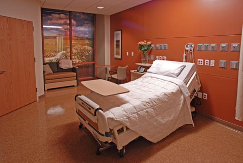
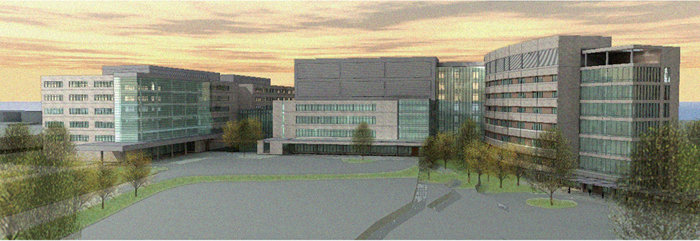
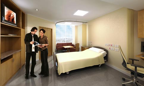
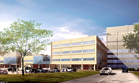
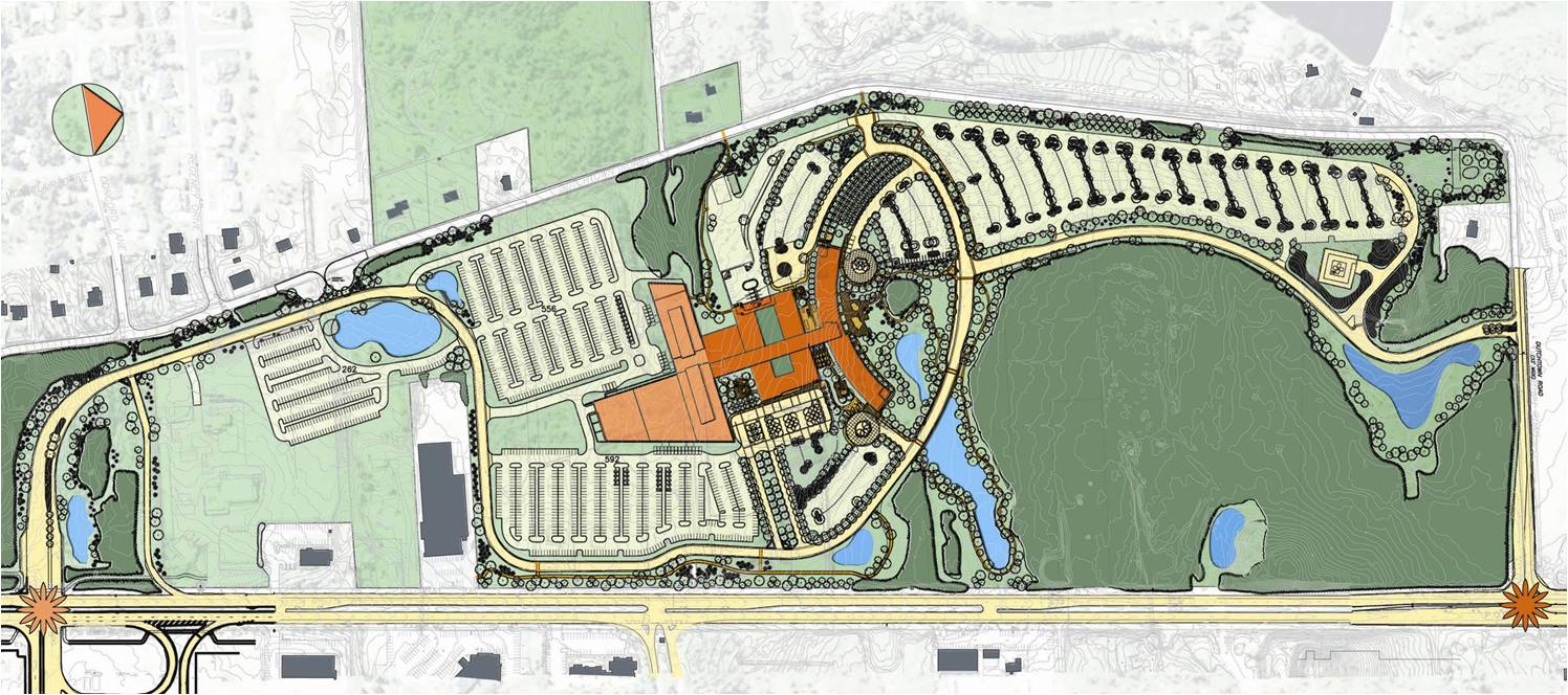
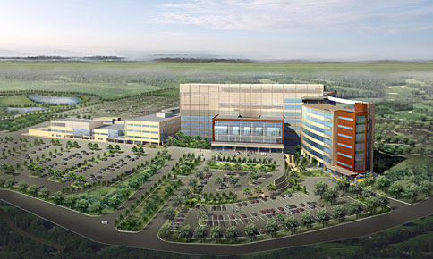
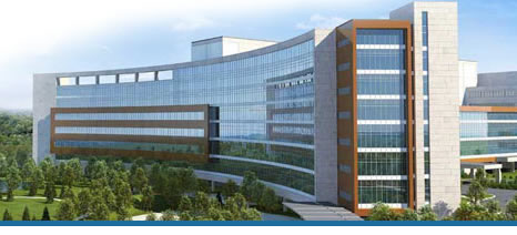
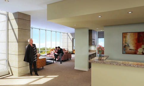
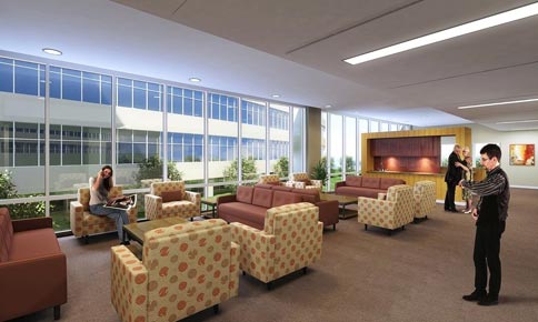
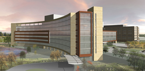
The new Virtua Replacement Hospital will be an eight story hospital with approximately 360 beds, each in its own private room. (Figure 1) The building is split into two main parts. (Figure 2) The first part is an eight story bed tower that contains the majority of the beds, while the southern building is a five story services building. The northern bed tower is a thin curved tower featuring a curtain wall along the north wall facing the rest of the site. (Figure 3) This particular shape helps sunlight enter the building allowing natural light to fill the patient rooms along this wall. (Figure 4) The five story services building is connected via a thin corridor with windows along both walls to allow light in. (Figure 5) The main features of this building are the three light wells, two of which act as courtyards, located in the center of the building. (Figure 6) They allow natural daylight to enter the center of the building, while also allowing the chance to get some fresh air without leaving the hospital. The designers also utilized the large, 120 acre, site to enhance the building. (Figure 7) The site contains various ponds, fountains, and existing wetlands, protected during construction. (Figure 8) |
|||||||||||||||||||||||||||||||||||||||||||||||||||||||||||||||||||||||||||||||||||||||||||||
| Building Enclosures: | |||||||||||||||||||||||||||||||||||||||||||||||||||||||||||||||||||||||||||||||||||||||||||||
|
|||||||||||||||||||||||||||||||||||||||||||||||||||||||||||||||||||||||||||||||||||||||||||||
Sustainability Features: |
|||||||||||||||||||||||||||||||||||||||||||||||||||||||||||||||||||||||||||||||||||||||||||||
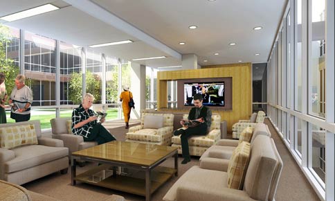
The Virtua Replacement Hospital takes advantage of a number of sustainable techniques. One of its main techniques is the use of natural day lighting to enhance the spaces. The building has a large curtain wall along the north facade allowing large amounts of light into the spaces. (Figure 9) The light not only limits the need for artificial light in the rooms along the windows, but it also enhances the space giving the occupants nice views of the site. (Figure 10) Another feature that this building uses are the green roofs/courtyards. (Figure 11) The building contains three light shafts that go down the southern building providing natural day lighting to the interior of the building. Two of these light shafts also act as a courtyard on the third and fourth levels, allowing occupants an opportunity to walk outside without leaving the safety of the building. The site also retains some of the wetlands that were located on the site prior to construction. (Figure 7) During construction protection was required around certain trees, and natural areas to insure that they would stay intact. For the areas that were not protected during construction, the designers called out various native grasses and plants to be used. The designers also anticipated a bus route to go to the hospital allowing visitors and staff to bus in rather than drive. Bike racks were also added for those who would rather bike to the hospital instead of drive or take the bus. |
|||||||||||||||||||||||||||||||||||||||||||||||||||||||||||||||||||||||||||||||||||||||||||||
| Structural: | |||||||||||||||||||||||||||||||||||||||||||||||||||||||||||||||||||||||||||||||||||||||||||||
| The main super structure of the building consists of structural steel columns, and beams. Floors are composed of composite lightweight concrete floor slabs on composite metal decking supported by wide flange beams. Typical bay sizes are 31'-4" x 29'-4" and approximately 30' x 32'. Columns are W14's for the entire height of the building. The foundation system of the hospital consists of concrete footings, with some footings resting on concrete piers. Geopiers were used on site in order to densify the sandy soil. The lateral system for the hospital is a combination of braced frames and moment resisting connections. | |||||||||||||||||||||||||||||||||||||||||||||||||||||||||||||||||||||||||||||||||||||||||||||
| Electrical: | |||||||||||||||||||||||||||||||||||||||||||||||||||||||||||||||||||||||||||||||||||||||||||||
Electrical service is received from Atlantic City Electric (ACE) at 12.47 KV. Currently there is only one utility service, however, a second service is planned to be installed in the future to increase reliability. The hospital has six 2,000 KVA unit substation to transform the utility service to 277Y/480 Volts. This power is then distributed through out the facility. For emergency power, the hospital will have three 1,500 KW diesel generators, with provisions to add a fourth generator in the future, when the hospital expands. In the event of a loss of power, these generators will come on line and backup essential electrical branches, which include life safety circuits, critical branch circuits, and equipment branch circuits. To provide uninterruptible power for the roughly 10 seconds when utility power is lost and the generators come on line, this hospital will have a rotary UPS. This is basically a large flywheel that is always spinning. If utility power is lost, it will continue to spin for about 30 seconds and generate power for that time while the generators are coming on line. |
|||||||||||||||||||||||||||||||||||||||||||||||||||||||||||||||||||||||||||||||||||||||||||||
| Lighting: | |||||||||||||||||||||||||||||||||||||||||||||||||||||||||||||||||||||||||||||||||||||||||||||
For the interior lighting design, the IESNA recommendations were followed. Recessed fluorescent fixtures of various types, sizes, and styles were used in the majority of the building. Electronically ballasted T8 linear, twin-tube long compact, and triple-tube compact fluorescent lamps were used as the building standard. Lighting for the parking and drive areas are provided by pole-mounted cutoff luminaires. The fixtures were classified as cut-off luminaires by the IESNA and have a peak distribution of less than 90 above nadir. Light trespasses are limited to not more than 0.5 foot-candles crossing the property line. The pole heights were determined by the Voorhees Township Code, and the heights determined the spacing and wattage for each lamp. Typical exterior lights are metal halides. |
|||||||||||||||||||||||||||||||||||||||||||||||||||||||||||||||||||||||||||||||||||||||||||||
| Mechanical: | |||||||||||||||||||||||||||||||||||||||||||||||||||||||||||||||||||||||||||||||||||||||||||||
Building heating, HVAC humidification, domestic water heating, and auxiliary steam demands for the hospital shall be served from a Central Utility Plant (CUP) hybrid heating system located primarily at the 5th floor mechanical area. The steam boilers provide primary service for the facility's demands. The plant capacity is based on an initial installation of 3 boilers to provide a total capacity of 1,500 BHP. The design facilitates future expansion of 2 additional units for a future capacity of 2,500 BHP total. The steam system also provides supplemental capacity and backup fuel redundancy for facility HVAC heating. Facility cooling will be provided by a centralized chilled water system. Primary chilled water generation will be provided at the CUP. Chilled water will be generated by electric drive, water-cooled, centrifugal water chillers. Base chiller sizing shall be nominal 1,000 cooling tons each. Base plant capacity shall be based on an initial installation of 3, 1,000 ton units to provide a total capacity of 2,000 ton, with one unit always reserved for redundancy. The facility is designed for a future expansion of 2 units to increase capacity to 4,000 tons. Cooling heat will be rejected through 4 induced-draft, cooling tower cells. The cooling towers will be high efficiency design with a nominal capacity of 833 cooling tons heat rejection per cell. There is also room for 2 future cells. There are 3 sets of air handling units. All the units are located in the 7th floor ancillary mechanical room. The first set contains 2 units and serves non-patient care areas such as Dietary, Environmental Services, Receiving, Lab and Maintenance. The second set contains 2 units and serves the Emergency Department, Peds Emergency, Surgery, C-Section operating rooms, the Pharmacy, and NICU. The Operating and C-Section rooms have pressure monitors to maintain positive room pressure, and will alarm if positive pressure is not maintained. The third set contains 6 units and serves the patient care areas. |
|||||||||||||||||||||||||||||||||||||||||||||||||||||||||||||||||||||||||||||||||||||||||||||
| Telecommunication: | |||||||||||||||||||||||||||||||||||||||||||||||||||||||||||||||||||||||||||||||||||||||||||||
| The telecommunication system of the building is on the low-voltage system and is being provided on cat-6 cables. A Public Address (PA) system is utilized in the building. The system is unique in that it must be able to withstand an earthquake, meaning it must remain in place without any separation of parts from the device when subjected to seismic forces specified, and the unit must be fully operational after the seismic event. | |||||||||||||||||||||||||||||||||||||||||||||||||||||||||||||||||||||||||||||||||||||||||||||
Figures: |
|||||||||||||||||||||||||||||||||||||||||||||||||||||||||||||||||||||||||||||||||||||||||||||
|
|||||||||||||||||||||||||||||||||||||||||||||||||||||||||||||||||||||||||||||||||||||||||||||
 |
The Virtua Health
Replacement Facility |
Voorhees, New Jersey |
|
Paul R. Stewart |
|
Structural Option |